DCC Commander is an application that allows you to communicate with your DCC-EX command station to control trains, accessories, and other DCC connected items. The application supports both iOS (Apple) and Android devices. DCC Commander supports both direct DCC-EX and JMRI WiThrottle connectivity.
This post assumes that you have built a DCC-EX command station and installed the firmware. If you have not completed those steps then please do so. The most challenging process of DCC-EX, assembling the DCC-EX command station, is now complete. Now it’s time to have some fun: verify your DCC-EX command station is fully functional and run some model trains.
Connecting the Track Power
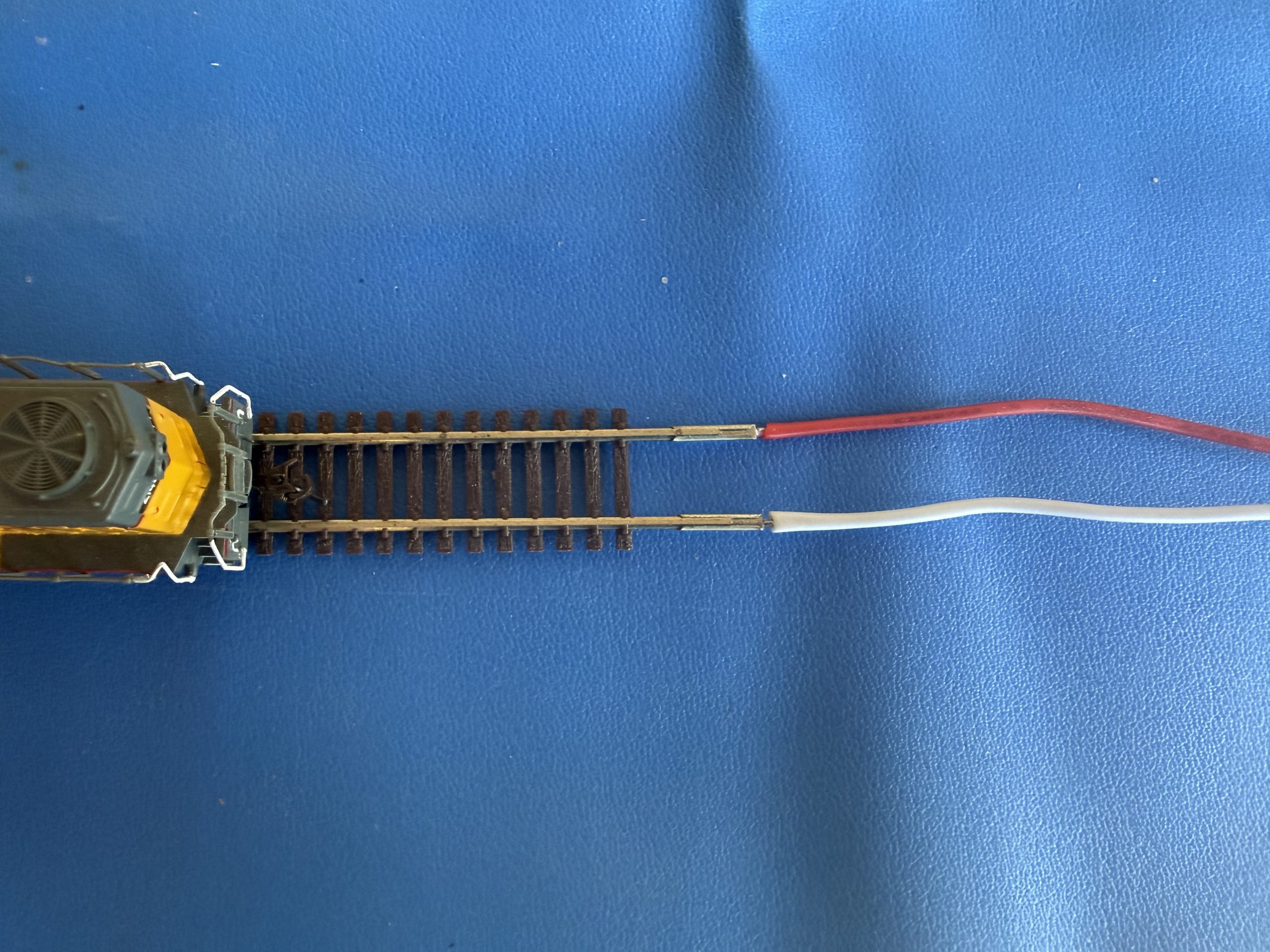
Connect the power leads from the DCC-EX motor shield to your model railroad track. Polarity does not matter. Either lead can be attached to either side of the track. Your choice will determine which direction is forward and which direction is reverse on your layout. You can always swap the leads if you choose.
From the previous post, you should have one positive lead (connected to PA+) and one negative lead (connected to PA-) on the motor shield.
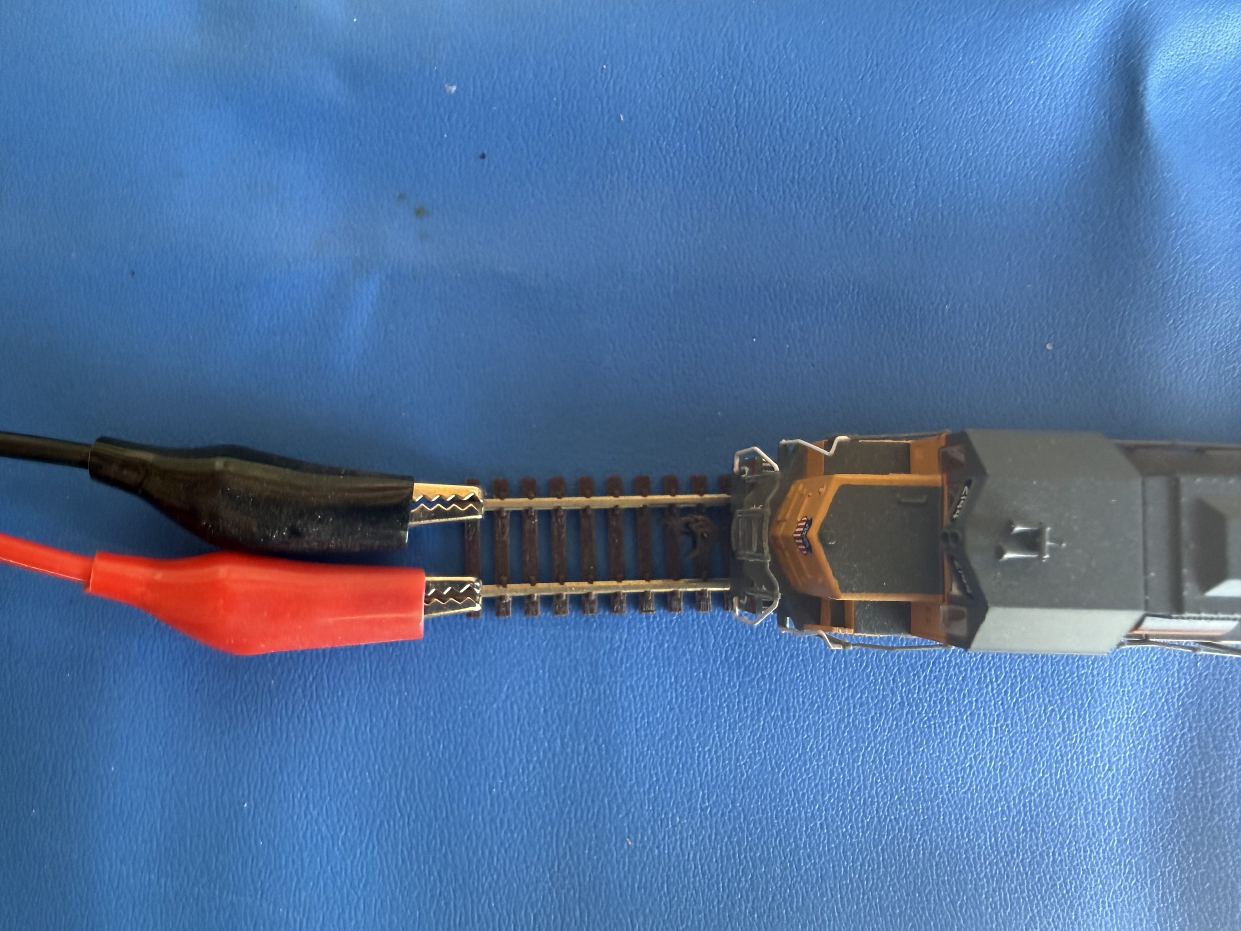
Connect each one of those leads to one of the rails of your track. You could solder the leads to the track or purchase a crimp-able alligator clips to make the connection easier.
Connecting the Power Supplies to the Wall
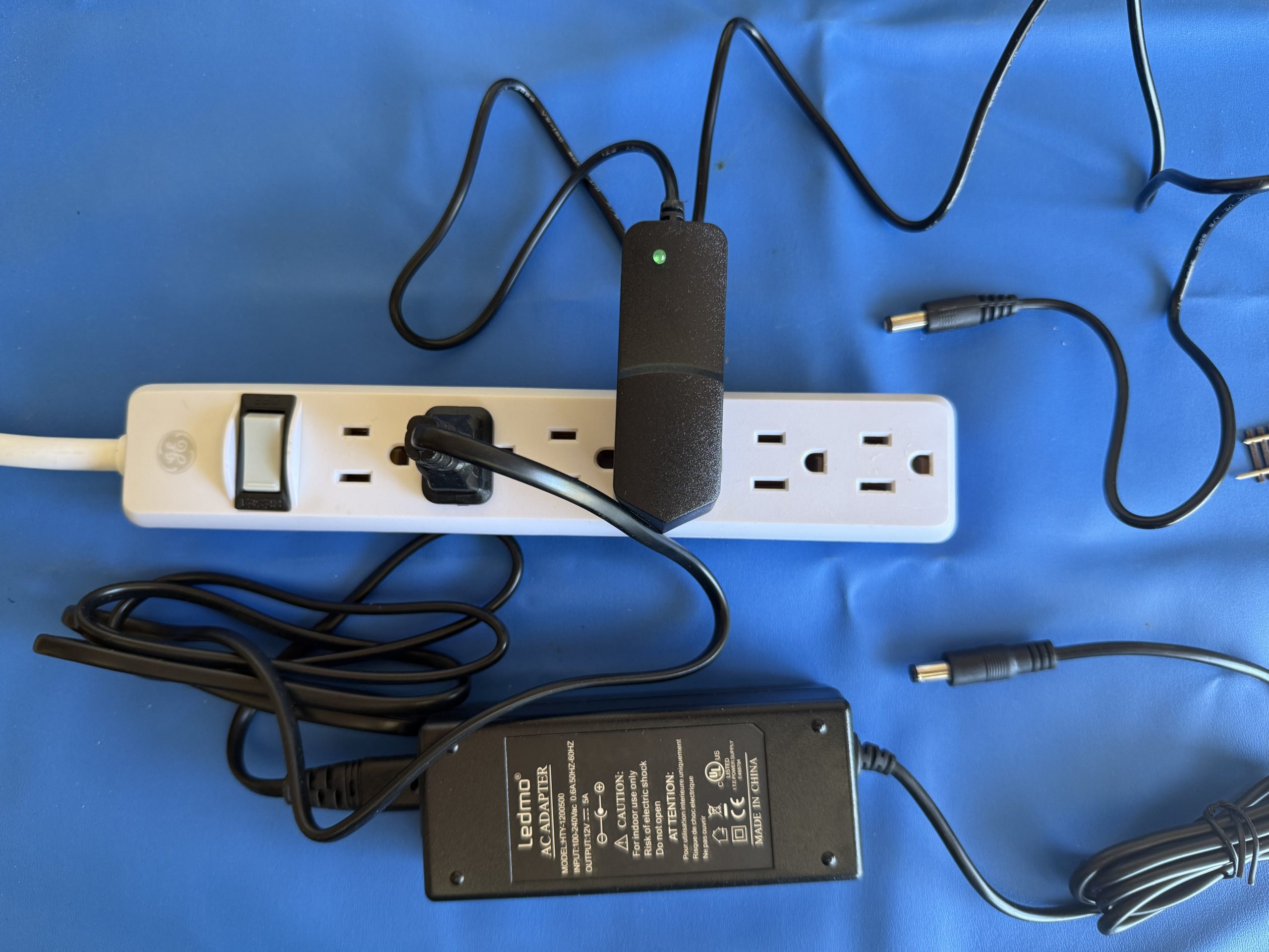
The DCC-EX command station has two power supplies. One for the track power (the larger 12 volt supply) and one for the Mega power (the smaller 9 volt supply). It’s recommended to plug the AC adaptors of both of those power supplies into a single surge protector with multiple outlets. This will allow you to power on the DCC-EX command station with the flip of a single switch on the surge protector.
Final Power Connections to the DCC-EX
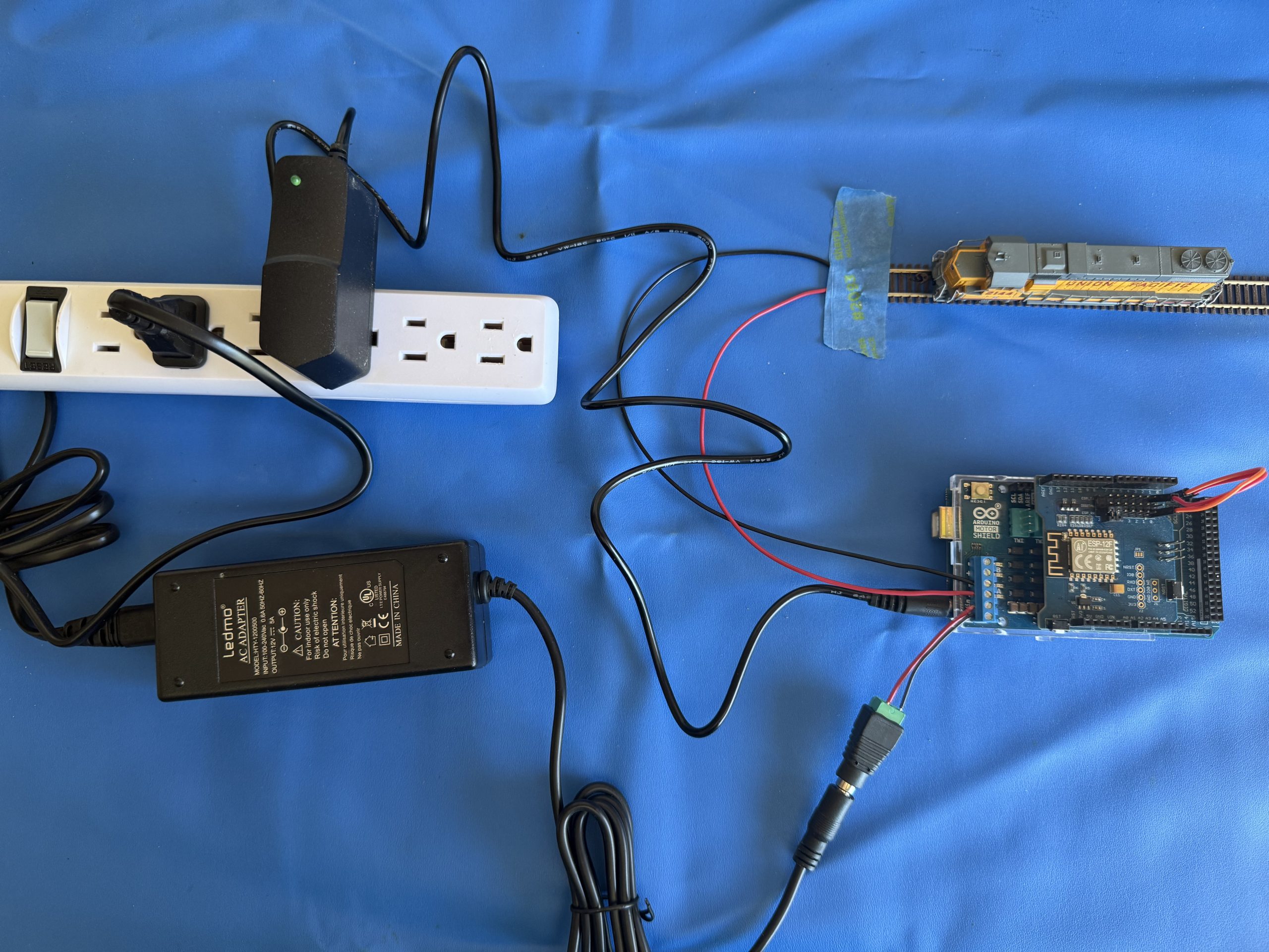
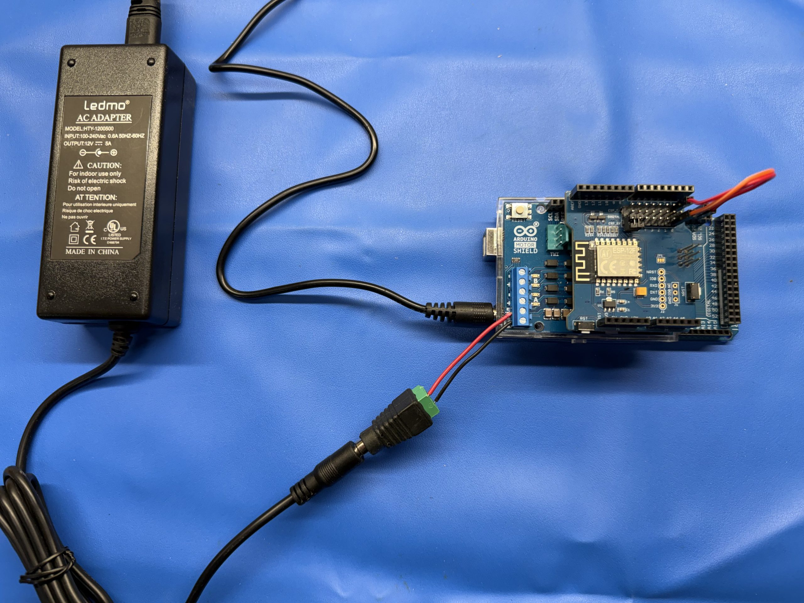
Connect the 12 volt power supply adaptor into the adaptor on the motor shield
Connect the 9 volt power supply adaptor into the Mega board
Note, the USB connection on the Mega board can be left open since you will be using WiFi to communicate with your DCC-EX and not USB
Power on Test
With all of the power connections complete you can now power on the DCC-EX command station via the switch on the surge protector.
This article assumes that you’ve assembled a DCC-EX command station in a well-defined manner as detailed in this article. The DCC-EX firmware is a set of instructions that tell the Mega how to generate the DCC timing and signals to control your model railroad layout. The easiest method to install the firmware on the DCC-EX hardware is to use the DCC-EX Installer. If you experience any issues with firmware installation and you are not using the well-defined DCC-EX then review the full DCC-EX Installer documentation to find settings that will support your specific needs.
Connect your assembled DCC-EX command station via USB cable to your system running DCC-EX Installer
A green LED on the Mega 2560 should illuminate telling you it’s powered-on and ready for a firmware update
The USB cable will supply power to the Mega 2560 to allow it to accept the firmware update. There is no need to plug in the 9V or 12V power supplies used for actually running trains
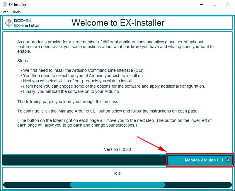
Launch the DCC-EX Installer you just downloaded from the DCC-EX website
Select “Manage Arduino CLI”
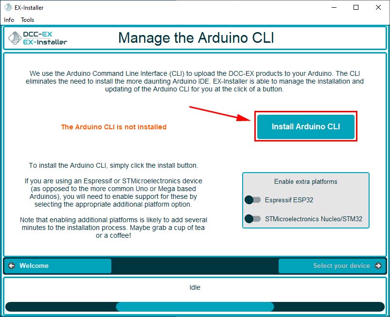
Select “Install Arduino CLI” if it is not already installed
The install process could take a minute, select “yes” if prompted to allow the installer to access your network
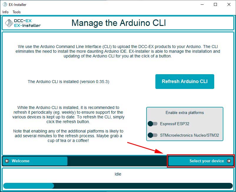
Select “Select your device” to continue
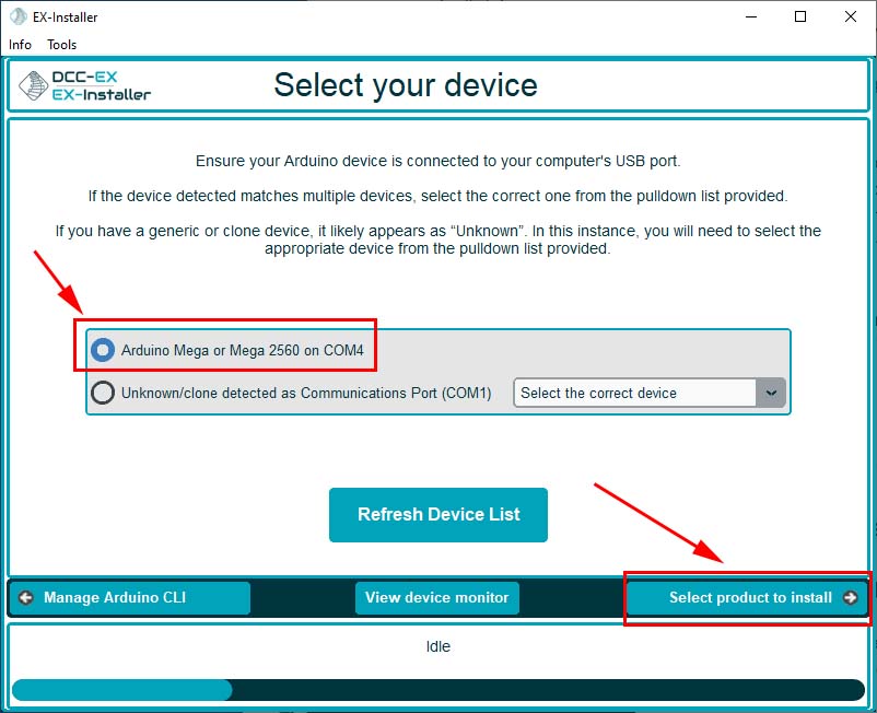
Since you used well-known parts to build your DCC-EX command station, the installer will automatically find your DCC-EX command station
Select “Arduino Mega or Mega 2560 on COM-X” (the above image shows COM4)
Select “Select product to install”
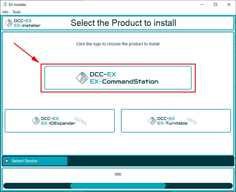
Select “DCC-EX, EX CommandStation”
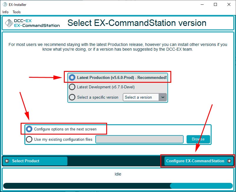
Select the default options “Latest Production – Recommended”
Select “Configure options on the next screen”
Select “Configure EX-CommandStation”
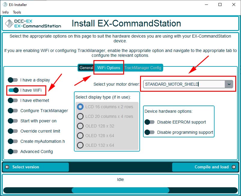
Select “I have WiFi”
Select “STANDARD_MOTOR_SHIELD” from the “Select your motor driver” list box
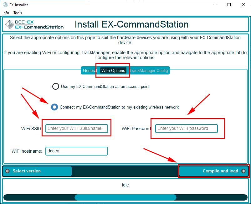
Lastly select the “Wifi Options” tab located on the top-center
Select “Connect my EX-CommandStation to my existing wireless network”
Enter the WiFi SSID for your wireless network
Enter the WiFi Password for your wireless network
Select “Compile and load”
Note
The WiFi SSID and password are the same you use to connect any wireless device to your network.
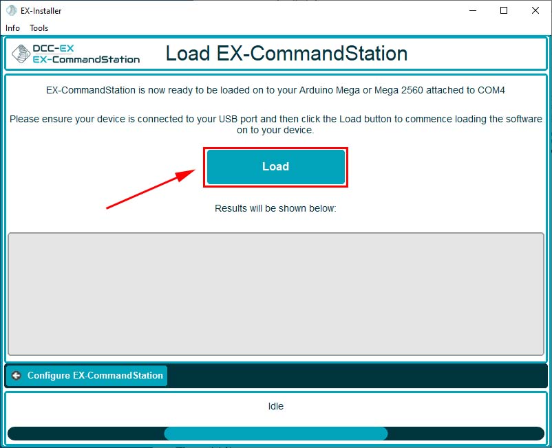
A confirmation prompt is displayed. Select “Load” to program the firmware on your DCC-EX command station
You should see a status bar at the bottom of the installer window and the Mega will blink a few times. Be patient!
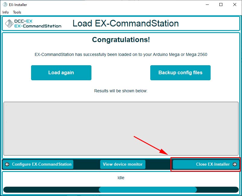
A final status window will be displayed
Congratulations! You’ve now programmed the firmware and you have a fully functioning DCC-EX command station.
DCC stands for Digital Command Control. It’s a standard used in model railroading that allows multiple locomotives to be independently controlled on the same section of track. National Model Railroad Association developed and maintains the DCC standards used by most manufacturers. For many hobbyists, DCC is the model railroad equivalent of moving from an old analog telephone system to a modern digital network. It transformed layouts from “control the track” to “control each locomotive individually.”
DCC Commander
DCC Commander is a mobile control center for Digital Command Control (DCC) model railroads, allowing operators to control locomotives, turnouts, routes, and layout functions from their iPhone, iPad, or Android device. Features include:
Controlling locomotives (up to 10 throttles per screen)
Throwing turnouts
Communicating with JMRI (WiThrottle-compatible communications) and compatible command stations
Communicating with DCC-EX command stations directly
Managing layout operations from a mobile device (iOS and Android)
Building layout schematics
Using swipe gestures to route locomotives along a layout
Building a DCC-EX command station is one of the easiest and most affordable ways to get started with DCC. If you’re comfortable with basic electronics or have built an Arduino project before, you’ll find the process straightforward. For a deeper dive into DCC-EX, including build-versus-buy considerations and the many available hardware options, visit the DCC-EX website.
If you’d rather skip the research, build a DCC-EX command station using a proven set of parts and get your model trains running, this guide is for you. The following sections describe a simple DCC-EX command station configuration that has become the “standard” DIY DCC-EX build because the parts are inexpensive, widely available, and well supported. You’ll find a complete parts list along with easy-to-follow assembly instructions.
If you’d rather skip assembling your own DCC-EX command station then you can purchase a pre-assembled unit directly from the DCC-EX group or one of their resellers.
Before You Start
This guide assumes you’re comfortable with basic electronics or you’ve assembled simple Arduino projects before but have never built a DCC command station. No soldering is required. You’ll only need a screwdriver, wire stripper and about 30 minutes. Genuine Arduino or compatible Mega 2560 boards both work fine.
Note
All assembly steps below are set apart as bullet-items for easy distinction between “wordy-words” and the steps required to assemble the DCC-EX. So, if you already have a good general understanding of assembling a DCC-EX then just look for the bullet-items and supported images.
Parts List
If you buy through these links, we may earn a small commission at no extra cost to you.
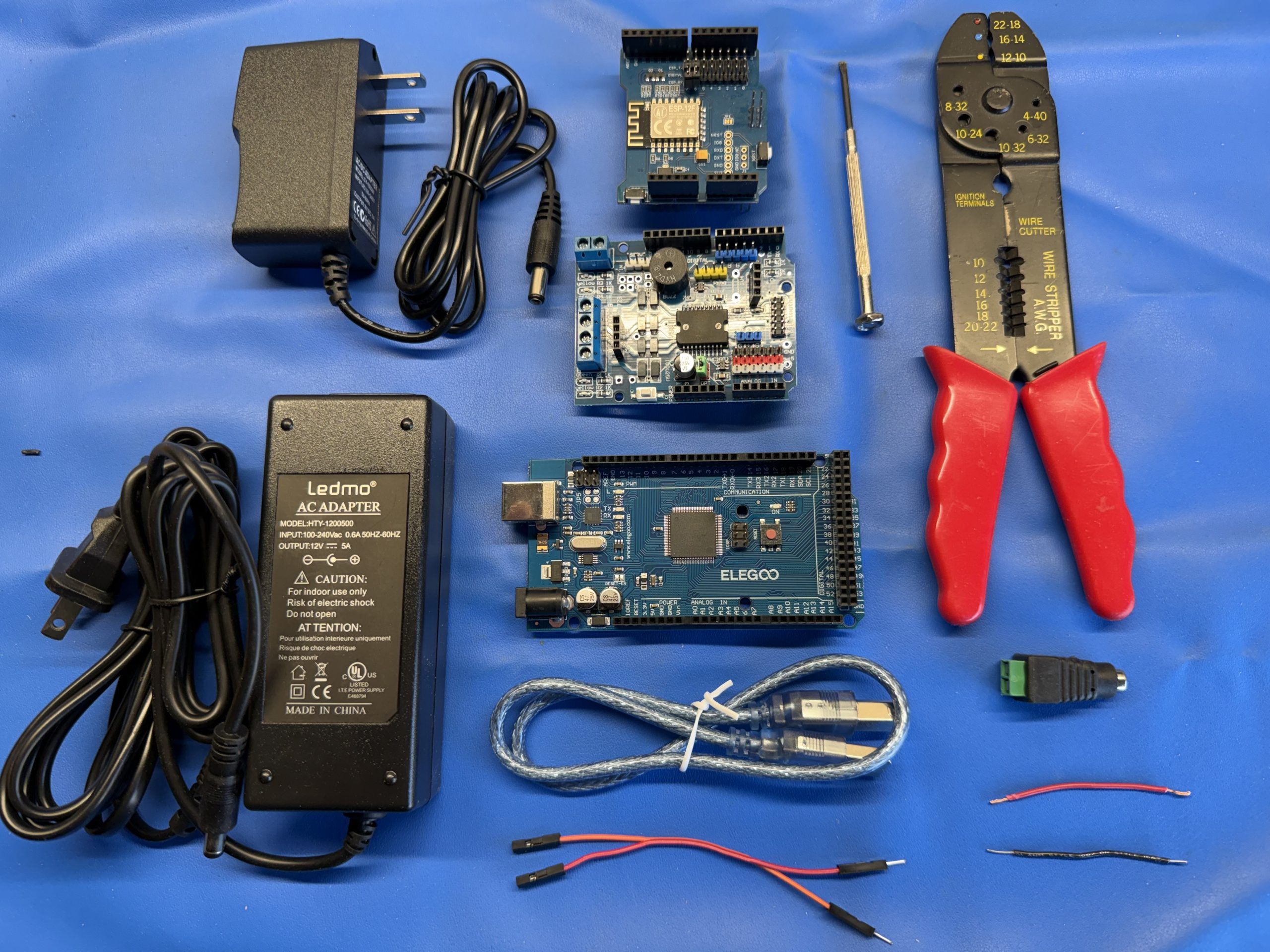
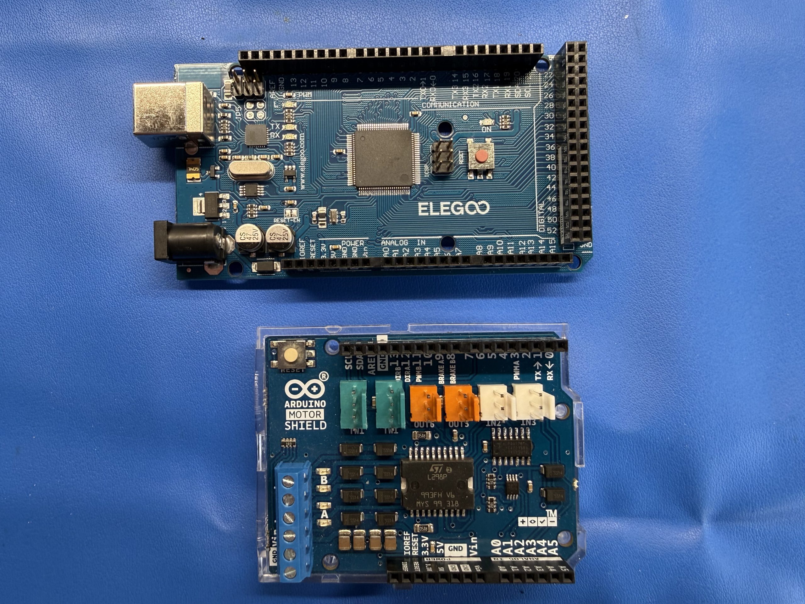
Notes: Genuine Arduino Mega 2560 boards and compatible clones both work well. The 9V power supply powers the Arduino and the electronics. The 12V supply powers the trains. They intentionally remain electrically separate as you will see below when you connect the Mega 2560 and the motor shield. Here is an image of all the parts you will need.
Connect Arduino to Motor Shield
Gather the Mega 2560 Microcontroller board and the Motor Shield board. The Mega 2560 is the brains behind the entire DCC-EX command station. It generates the timing and signals required for DCC to control your layout. The motor shield is the brawn behind the DCC-EX command station. It generates the necessary power (voltage and current) and transfers the DCC signal to your layout to control your trains.
The motor shield plugs directly into the Mega 2560 and sits on top of it.
The power output block (the blue, or sometimes green, terminal block with 6 screws) on the motor shield should face the same direction as the USB port on the Mega 2560 board
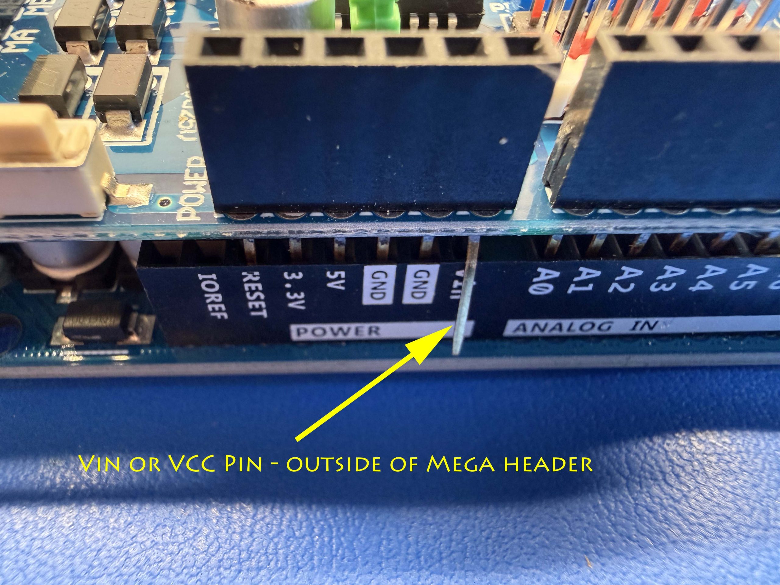
NOTE: Ensure the power pin labeled “Vin” or “VCC” is NOT aligned within the Mega 2560 board (see image below – that pin should hang outside of the Mega 2560 female header. This is so the power of the Mega 2560 board and the motor shield can remain isolated from each other)
Carefully align all pins and verify that every pin is entering its matching socket before pressing the boards together.
The final result should look like the image below (take note of the single Vin/VCC pin which is NOT sitting in the female header)
Warning!
Aligning the Vin/VCC pin is the single most important step in the build. If the Vin/VCC pin is inserted into the Mega header, the Arduino and motor shield power supplies become connected together, which can damage the hardware.
Here’s an up-close image of the motor shield’s Vin/VCC pin slightly bent out so it does not sit in the female header of the Mega 2560 board. You can cut-off that extending pin if you prefer.
Connect WiFi to Motor Shield
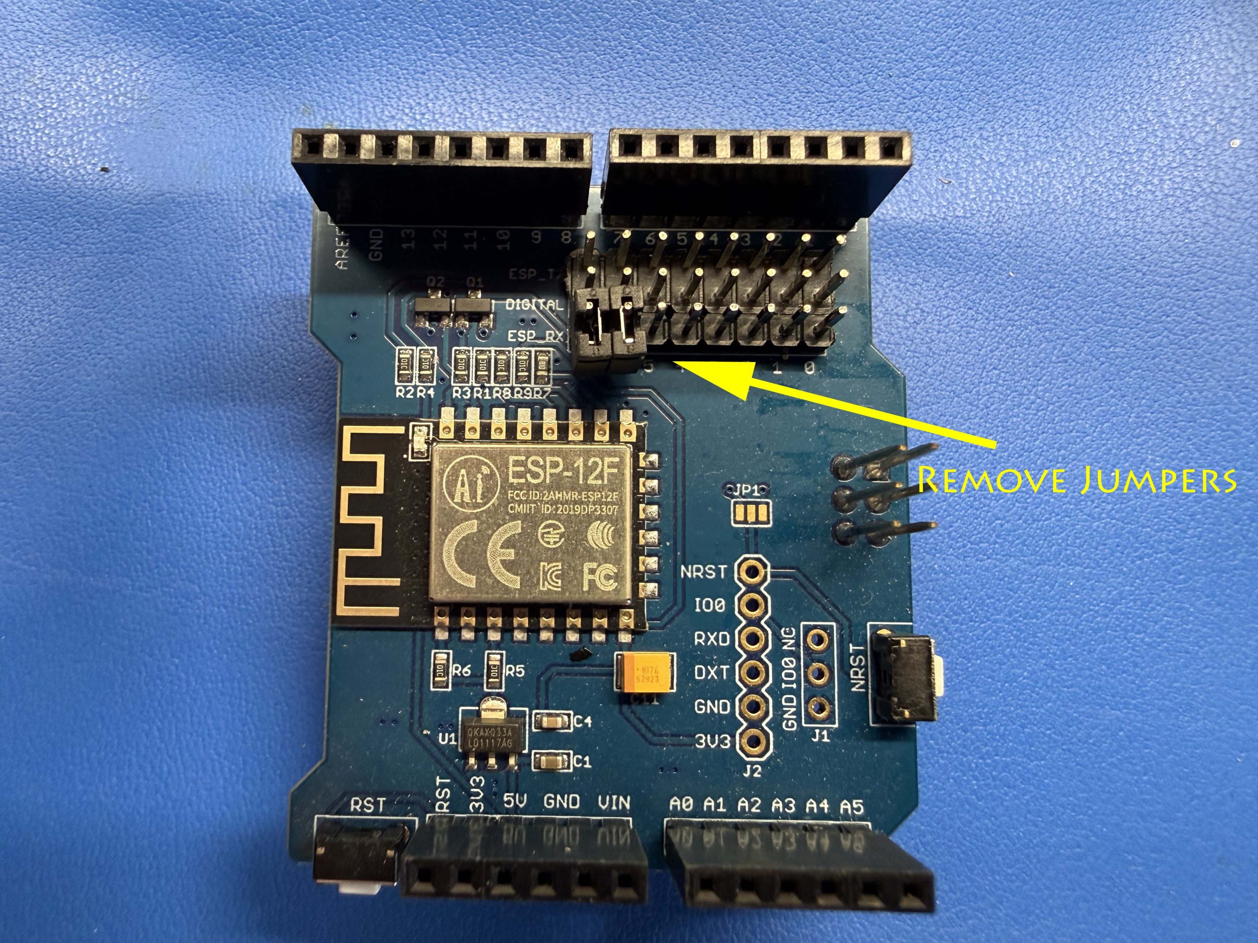
Remove any jumpers on the WiFi shield’s 24-pin header (you can either remove the small black jumpers completely or have them hanging off a single pole on the header). These jumpers are only used when programming the ESP8266. They must be removed for normal operation with DCC-EX.
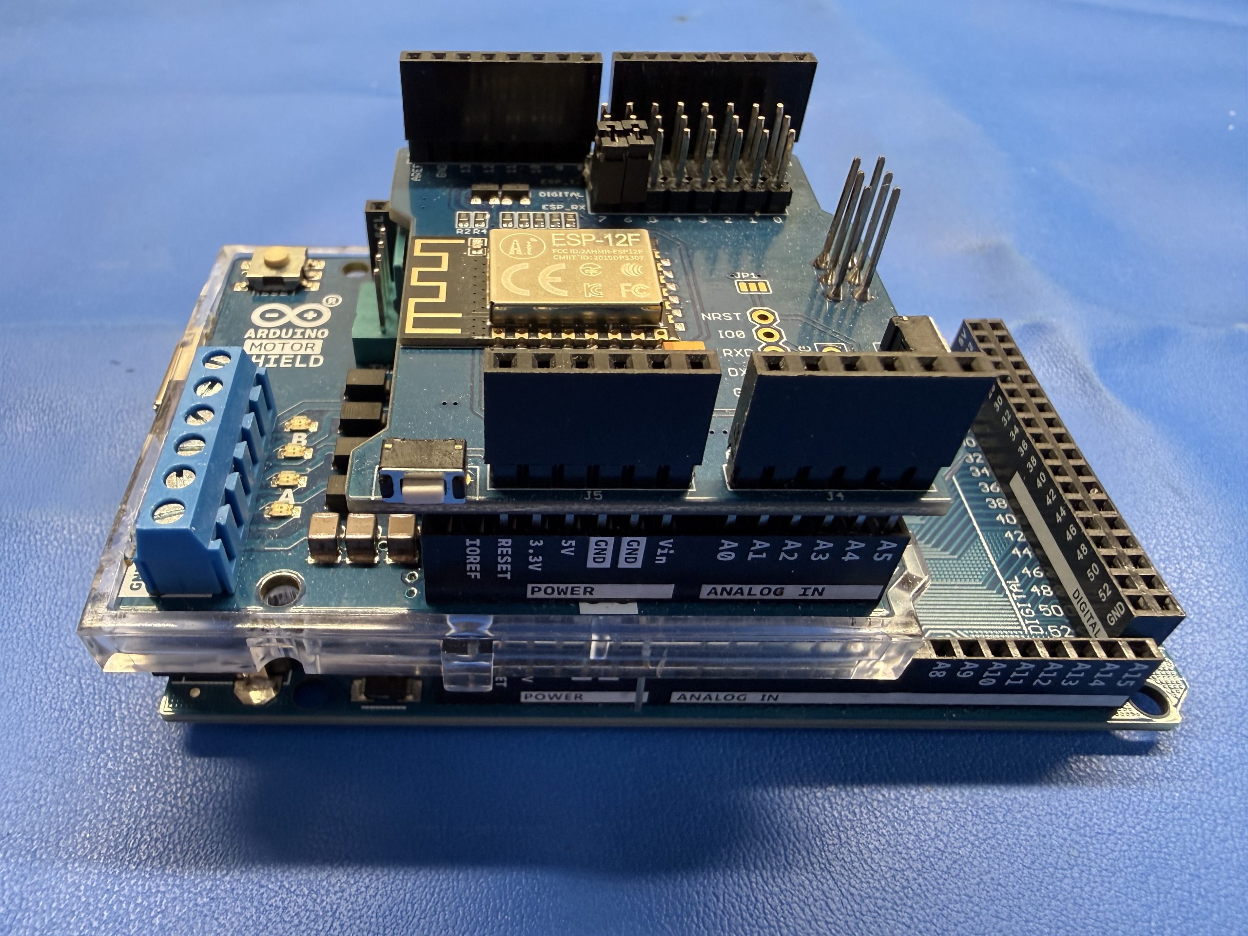
The WiFi board sits on top of the Motor Shield
The 24-pin header on the WiFi shield must be positioned opposite the USB port on the Mega 2560 board
Carefully align all pins and verify that every pin is entering its matching socket before applying pressure to the WiFi shield (note the pins might not seat entirely within the female headers – this is okay)
Connect Jumper Wires
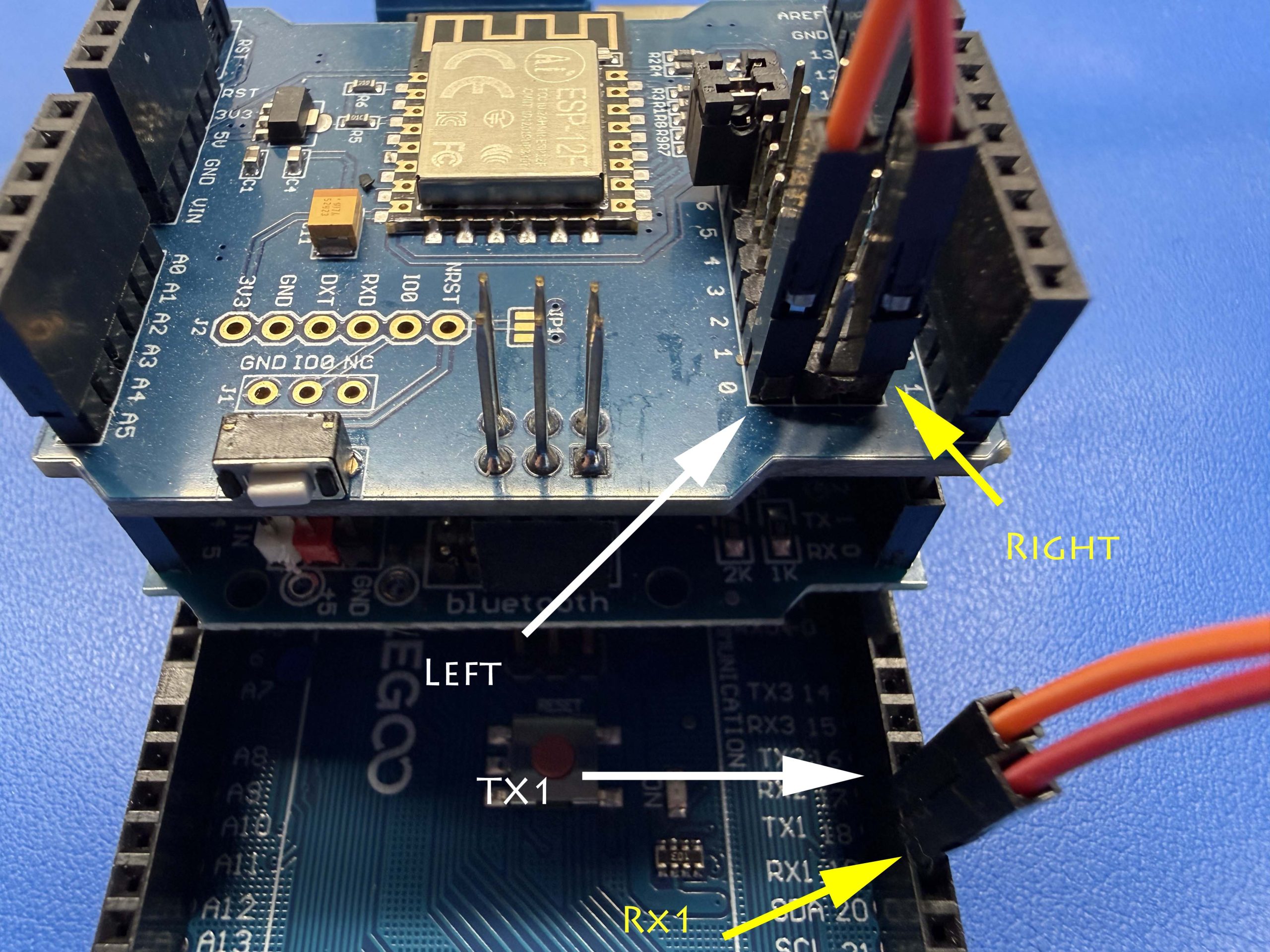
Two jumper wires are required to connect the Mega’s serial port to the ESP8266 WiFi module. TX1 transmits data from the Mega to the WiFi shield, while RX1 receives data back from the WiFi shield. This allows the Mega to communicate with a wireless throttle, such as DCC Commander, via a WiFi network connection.
Connect one jumper wire from pin 18 (labeled TX1) on the Mega 2560 board to the left-most pin on the first row of the 24-pin header of the WiFi shield (see the text and arrows in white on image below)
Connect a second jumper wire from pin 19 (labeled RX1) on the Mega 2560 board to the right-most pin on the first row of the 24-pin header of the WiFi shield (see the text and arrows in yellow on image below)
Note
The left-most and right-most pins are referenced when holding the Mega 2560 board such that the USB port is pointing upwards and the WiFi shield pointing towards you (also, see arrows on image below)
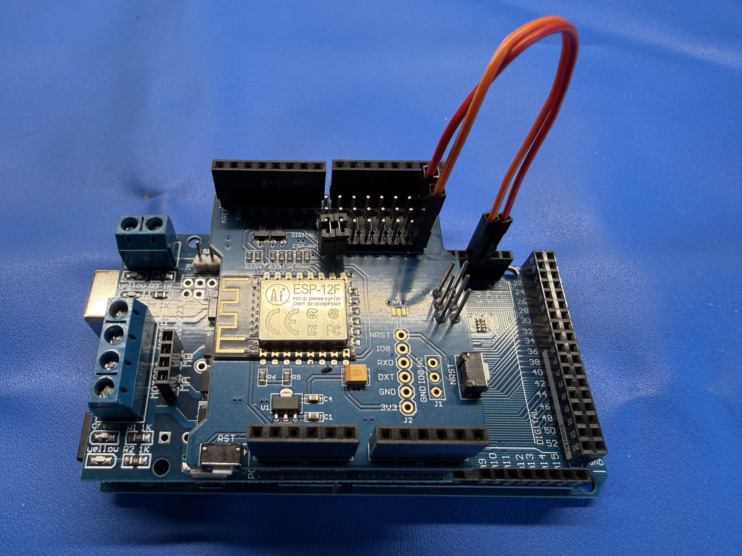
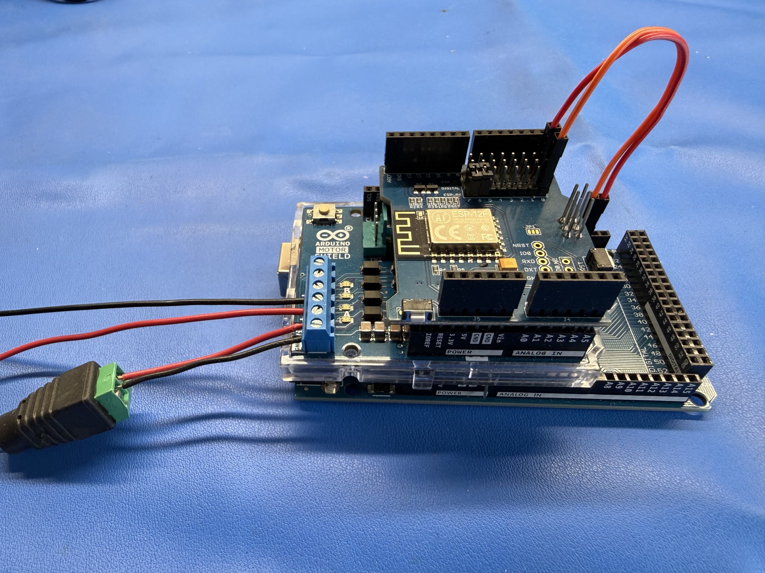
Jumper wires connected to the Mega 2560 and WiFi shield:
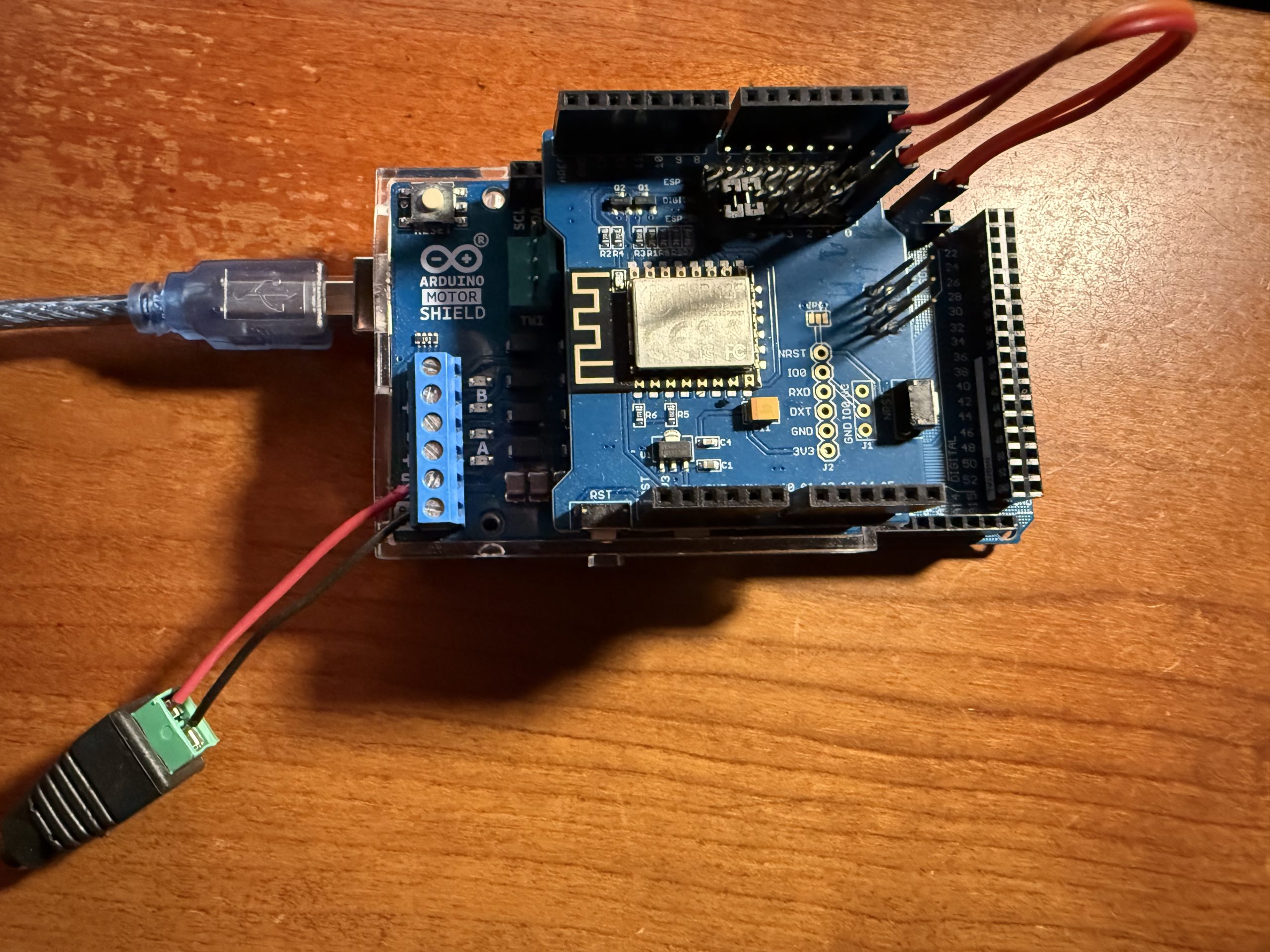
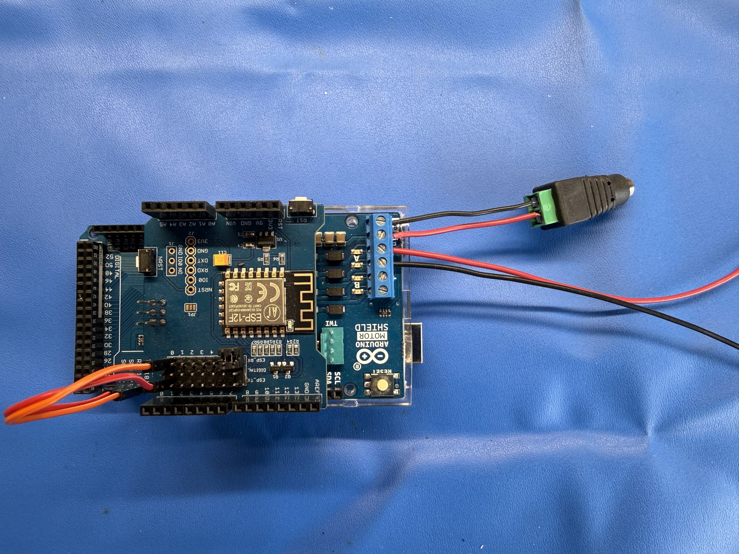
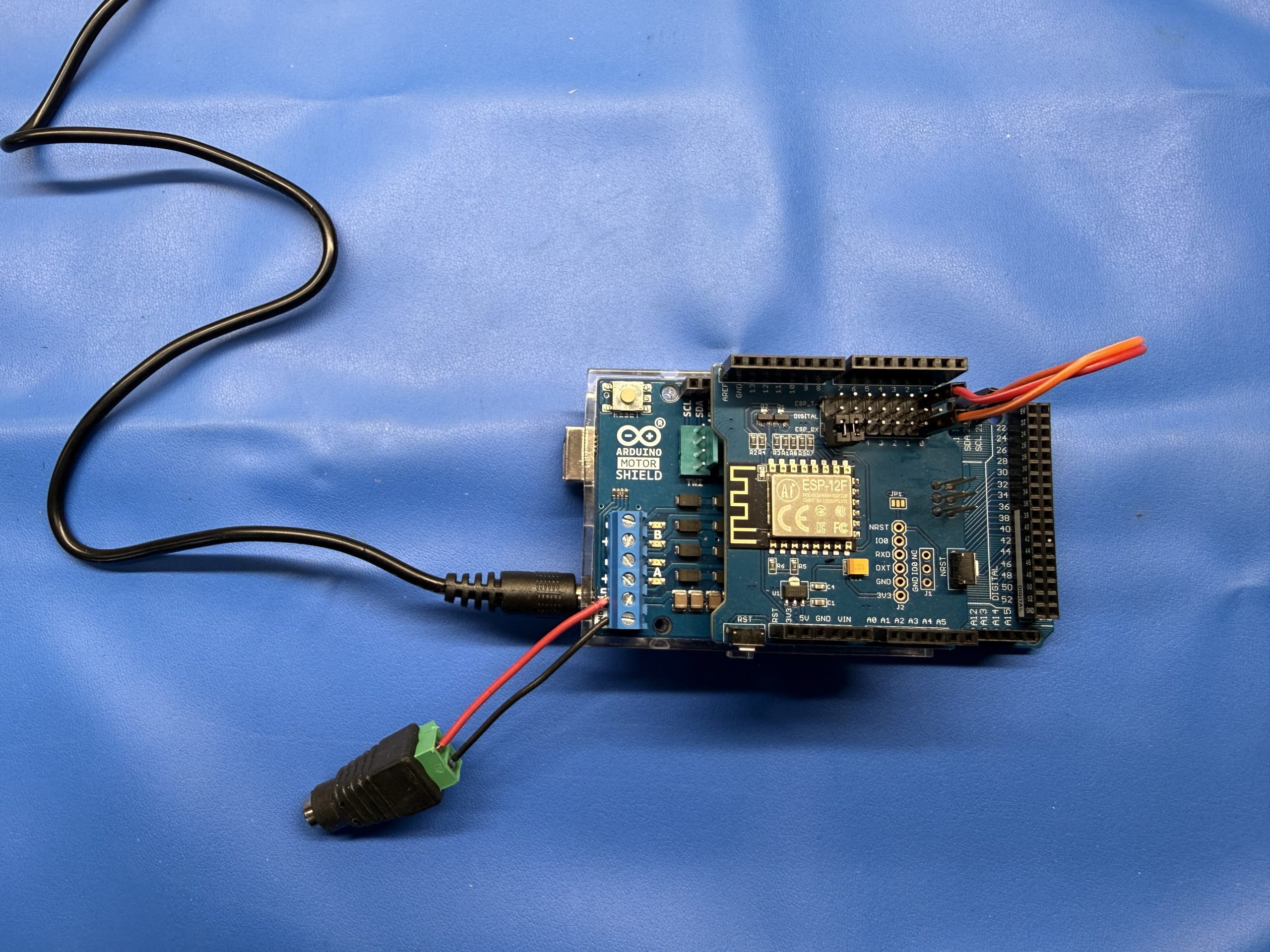
The assembled DCC-EX command station:
Assemble Power Plug
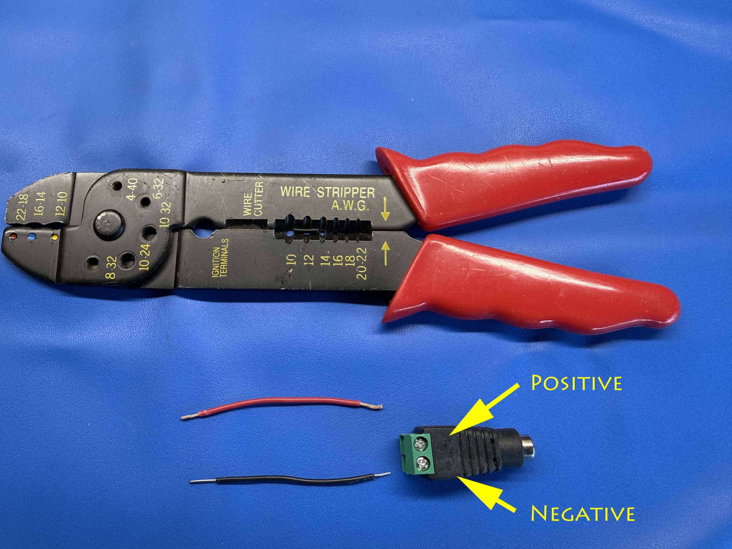
Assemble a power plug to be used for easily plugging in the power supply for the layout to control your DCC trains and accessories.
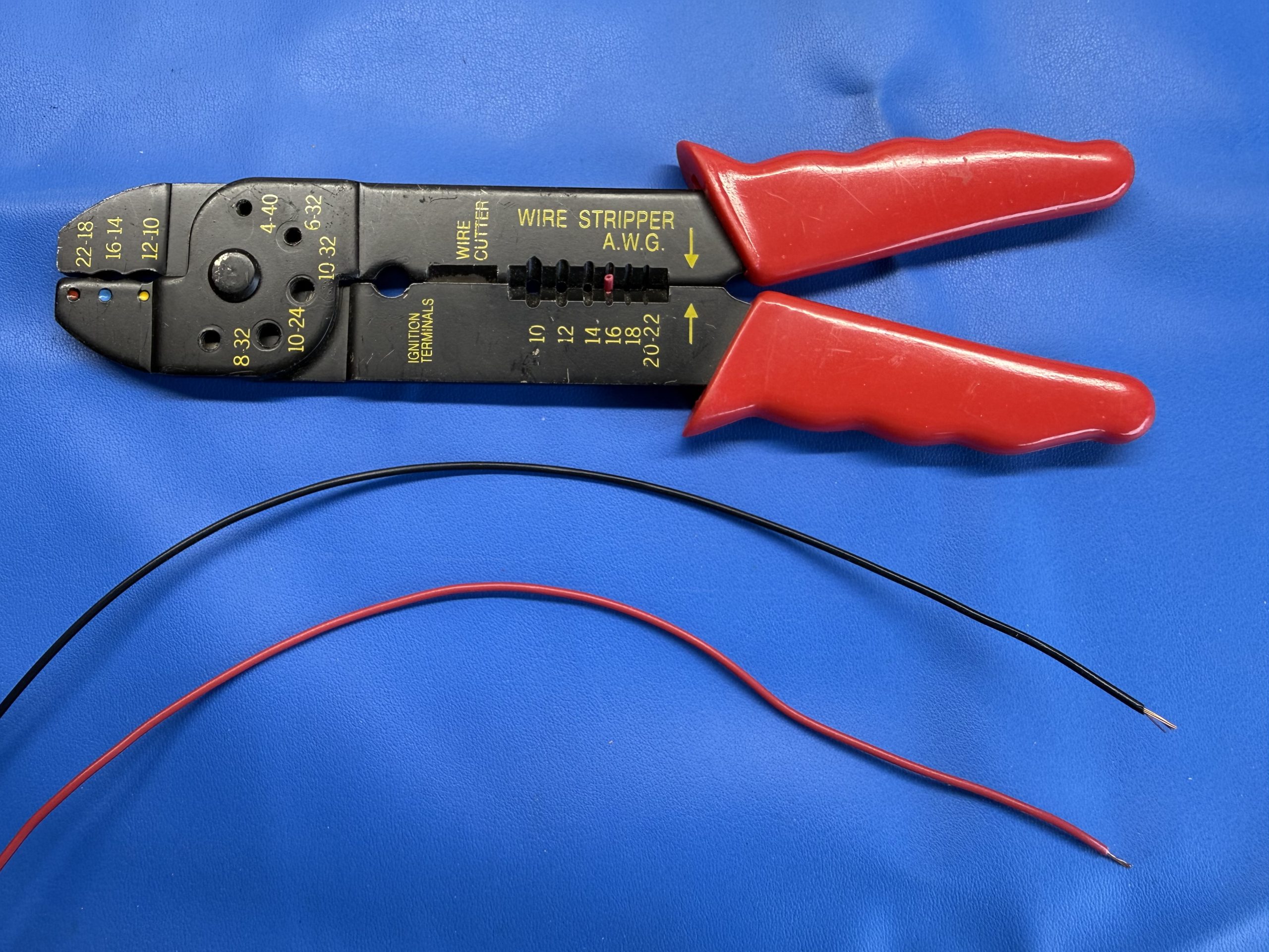
Cut 2 wires about 4″ long using the 20 gauge wire and strip about 1/4″ of insulation from both ends
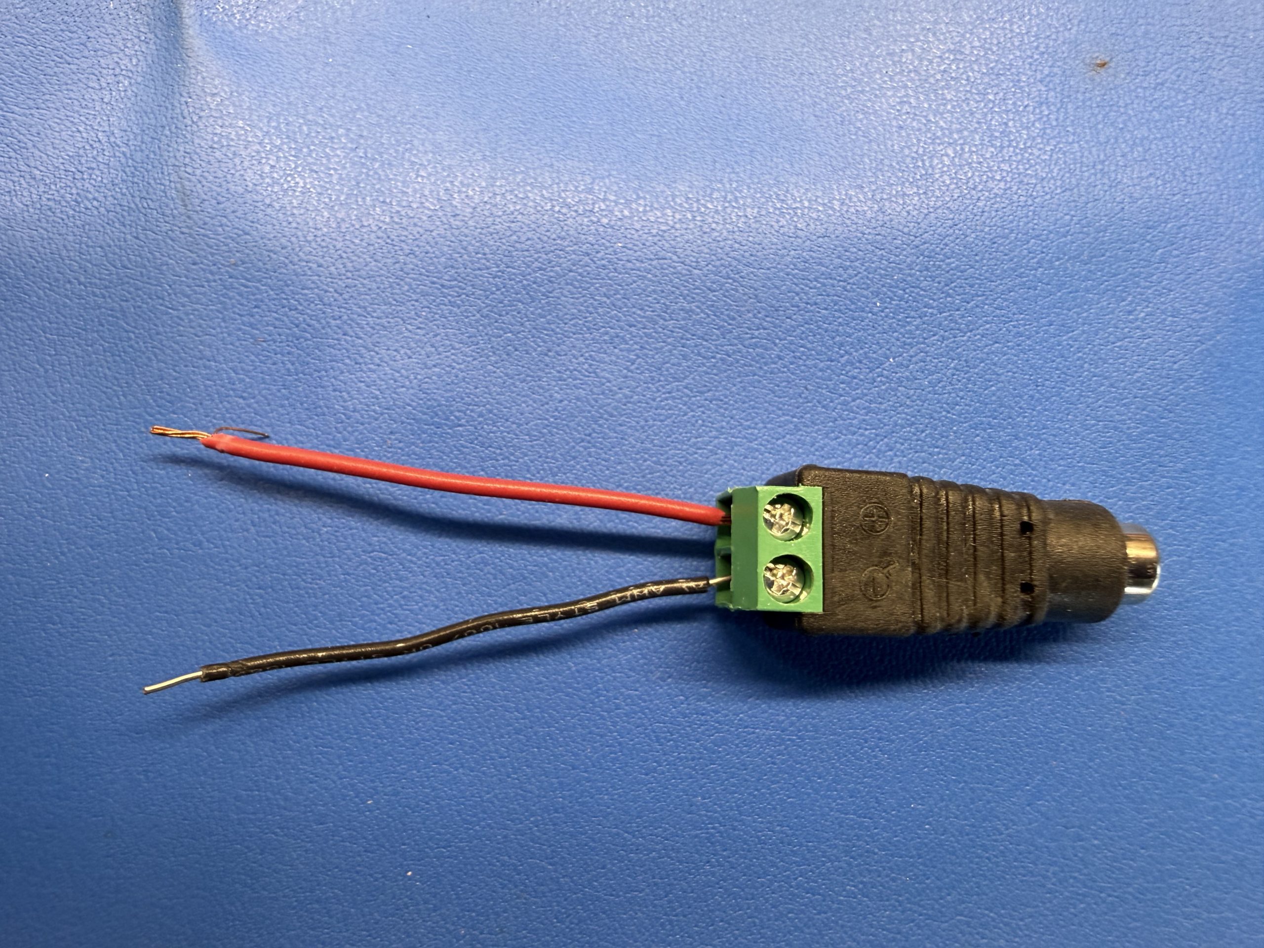
Loosen the screws in both of the terminals of the power connector
Insert the wires into the slots below the screws
Polarity matters, note the + and – on the power connector above the screws (for consistency, use the red wire for the + connector and the black wire for the – connector)
Tighten-down the screws in both of the terminals of the power connector to secure the wires
Gently tug each wire afterwards to ensure it is secure
Ensure no exposed copper is visible
Cut Track Power Wires
You will need wires to connect the output of the motor shield to your layout to control trains and accessories.
Cut 2 (or optionally, 4, if you’re going to use a programming track in addition to the Main track) pieces of 20 AWG wire long enough to reach from the DCC-EX to the track on your layout (for consistency, use red wire for + and black for – )
Strip about 1/4″ of insulation from all ends of the wires
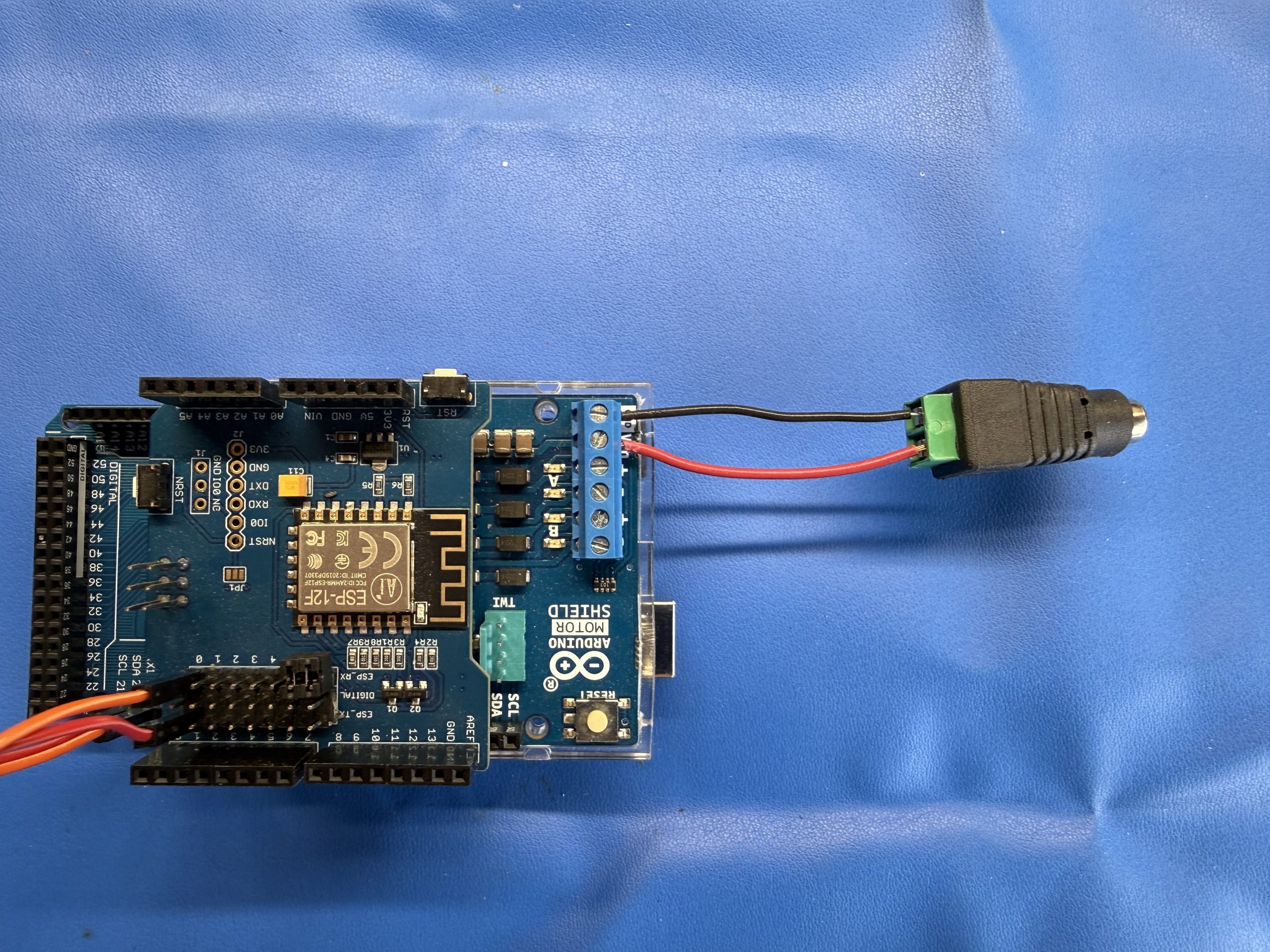
Connect Power Plug to Motor Shield
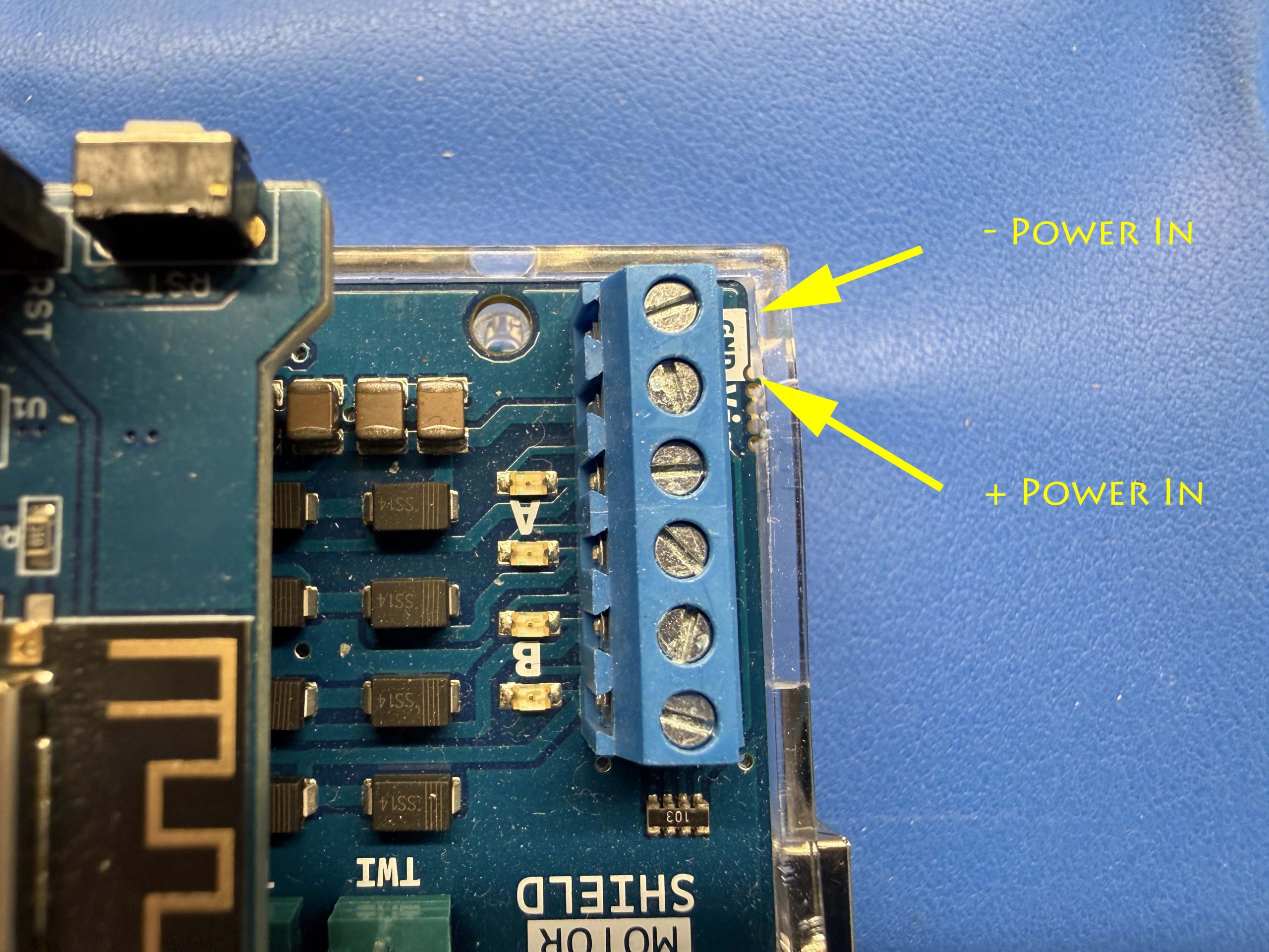
On the blue power terminal strip on the motor shield, locate the Power In + and Power In – poles (these should be located just above the USB port on the Mega 2560)
Loosen the screws in both of the terminals
Insert the wires from the power plug into the slots below the screws
Polarity matters, note the + and – on the power connector above the screws
Tighten the screws in both of the terminals of the power connector
Gently tug each wire afterwards to ensure it is secure
Ensure no exposed copper is visible
Connect Main Track Power Lead Wires to the Motor Shield
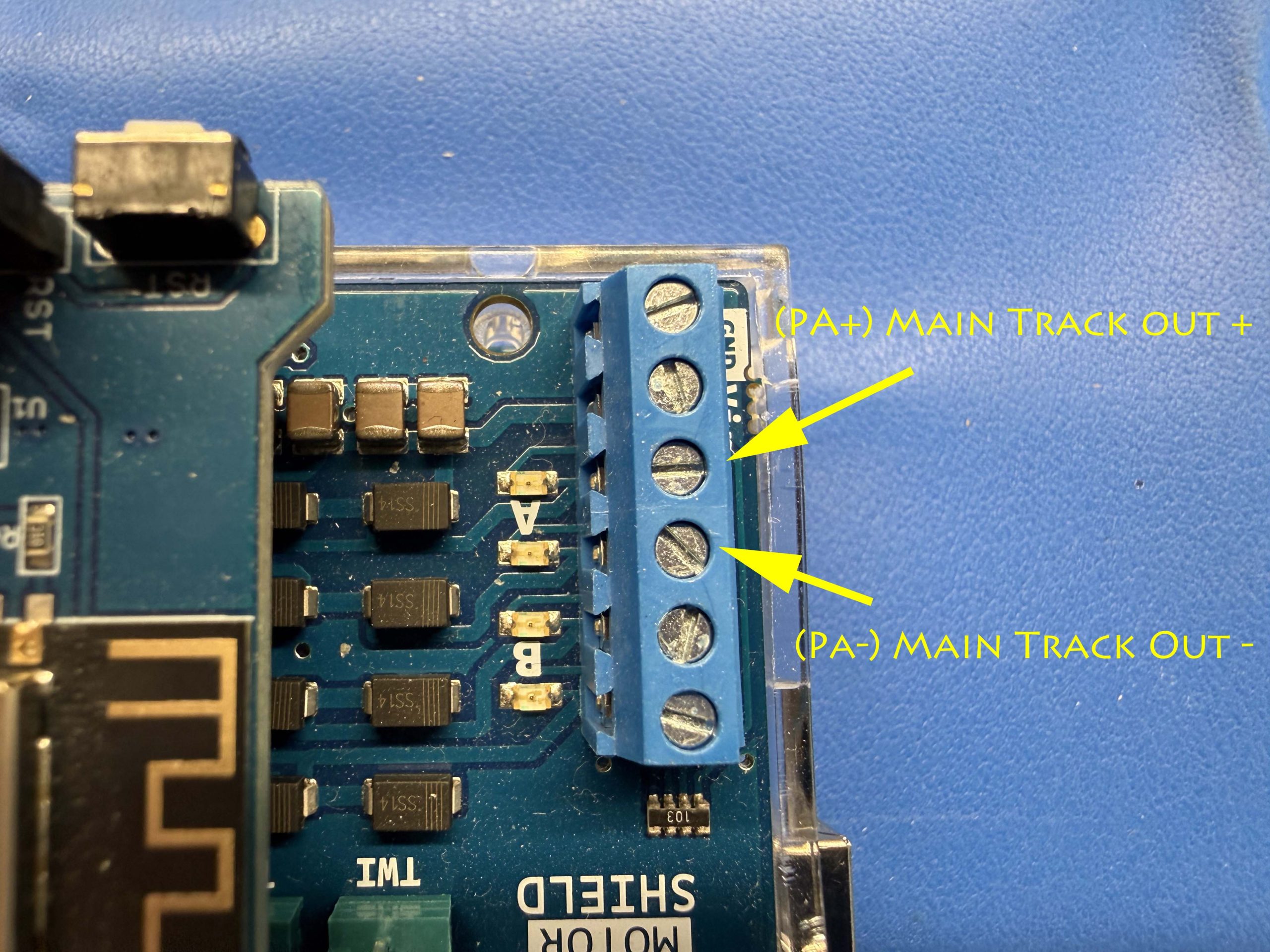
On the blue power terminal strip on the motor shield, locate the PA + and PA – poles (these should be located just above the USB port on the Mega 2560)
Loosen the screws in both of the terminals
Insert one black wire (on the – pole) and one red wire (on the + pole) below the screws
Polarity matters, note the + and – on the power connector above the screws
Tighten the screws in both of the terminals of the power connector
Gently tug each wire afterwards to ensure it is secure
Ensure no exposed copper is visible
[Optional] Connect Programming Track Lead Wires to the Motor Shield
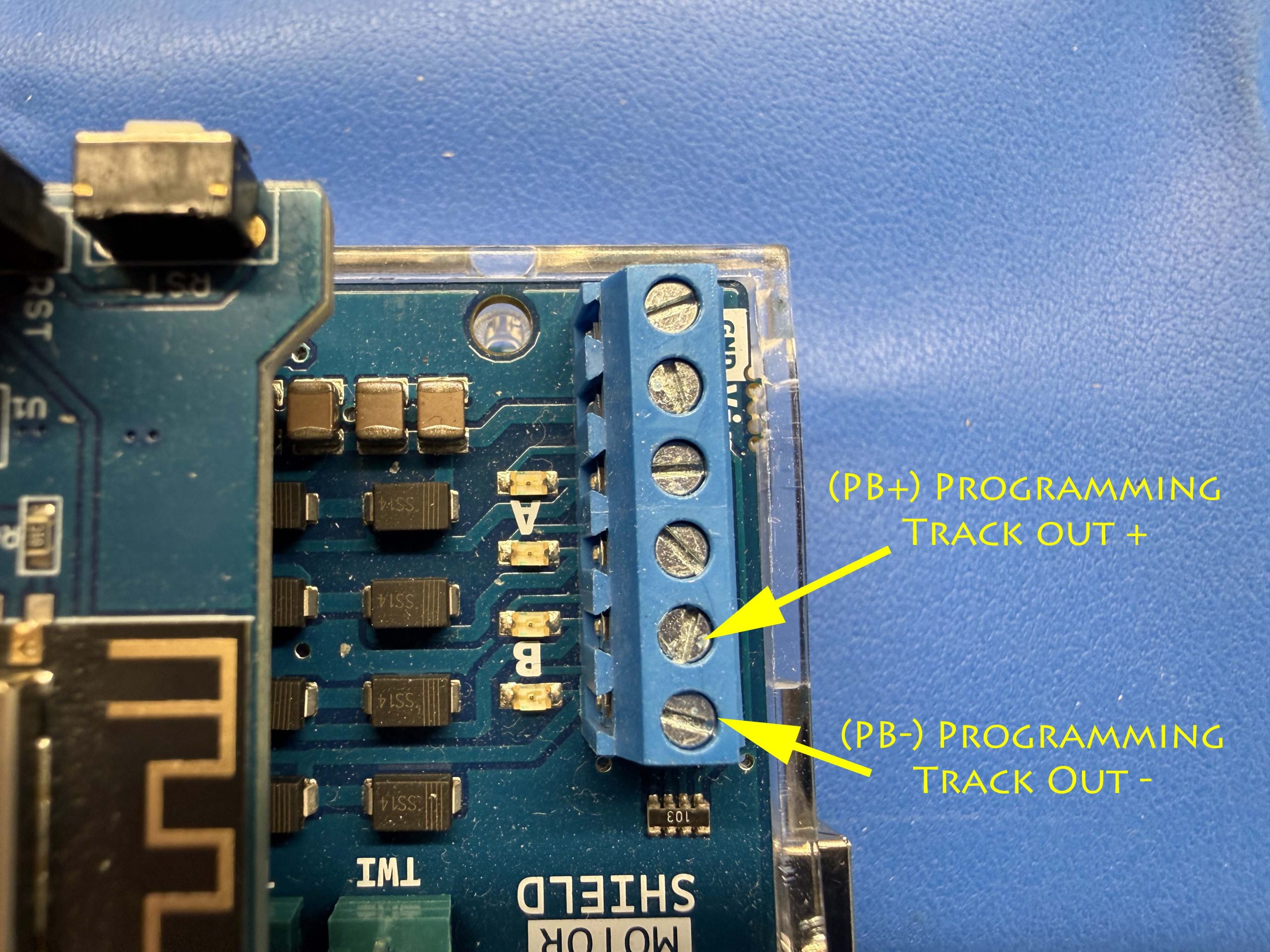
On the blue power terminal strip on the motor shield, locate the PB + and PB – poles (these should be located just above the USB port on the Mega 2560)
Loosen the screws in both of the terminals
Insert one black wire (on the – pole) and one red wire (on the + pole) below the screws
Polarity matters, note the + and – on the power connector above the screws
Tighten the screws in both of the terminals of the power connector
Gently tug each wire afterwards to ensure it is secure
Complete Hardware
Congratulations! Your DCC-EX hardware is built and ready to use. It should look something like this:
Final Hardware Checklist
Before applying power, confirm each item below:
✅ Motor shield fully seated on Mega 2560
✅ Vin/VCC pin NOT inserted into Mega 2560
✅ WiFi shield jumpers removed
✅ WiFi shield fully seated on motor shield
✅ TX/RX jumper wires installed from Mega 2560 to WiFi shield
✅ Power plug polarity correct
✅ Main track and programming track wires polarity correct
Initial Power-Up
A quick test to verify everything is looking good. After applying power, if you feel any heat from any of the boards or see any visible smoke then disconnect power immediately and review the checklist again. If you saw smoke then you’ll likely have to replace the part that smoked – extremely rare though!
Power on the Mega using the 9V power supply first on its own
You should see a solid green LED light up on the Mega and possibly some blue LED’s blink on the WiFi shield but not much else to see yet
While keeping the Mega 9V power supply plugged in, plug in the motor shield 12V power supply
You should see the 4 LED’s next to the blue power header on the motor shield blink. Pressing the small toggle button on the motor shield should reset the motor shield and blink those lights again. Not much else to see yet
If the LED’s light up then you can claim success. Congratulations!
Next Step
The next step is installing the DCC-EX firmware. Once that’s done, you’ll be ready to connect your command station to your layout and begin running trains.